
You can now insert a cap plate in steel joints with only a few clicks. You can enter the data using the known definition types "Offsets" or "Dimensions and Position". By specifying a reference member and the cutting plane, it is also possible to omit the Member Section component.
This component allows you to easily model cap plates on column ends, for example.
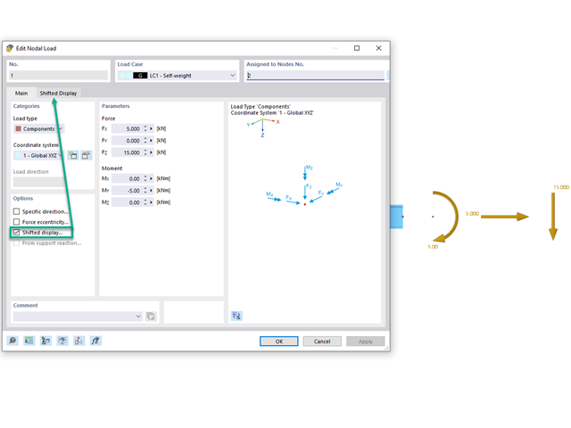
Would you like to display nodal loads or load components that act on one point next to each other? Then use the "Shifted Display" option. This allows you to define offsets in the x, y, and z directions, as well as the size and spacing.
Go to Explanatory Video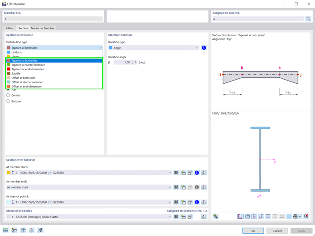
There are seven new cross-section distribution types available for members (including arrangement function for aligning to a straight edge):
- Tapered at both sides
- Tapered at start of member
- Tapered at end of member
- Duopitch
- Offset at both sides
- Offset at start of member
- Offset at end of member
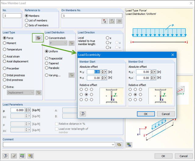
You can define eccentricities for member loads of the load type 'Force'. You can apply the load eccentricities by means of an absolute or relative offset.
We recommend using the large deformation analysis to consider all effects of eccentric loads.